I’ll show you how to properly disassemble the 4VES-7-40P compressor. Begin by depressurizing the compressor to do so you will need to extract the refrigerant via the Schrader valve. Before disassembly, you also need to drain the oil.
The screws on the cover of the compressor terminal box are then listened to using a screwdriver, the cover is taken off and the protective conductor on the cover is unscrewed the motor protection device can then be removed and the terminal box is taken off.
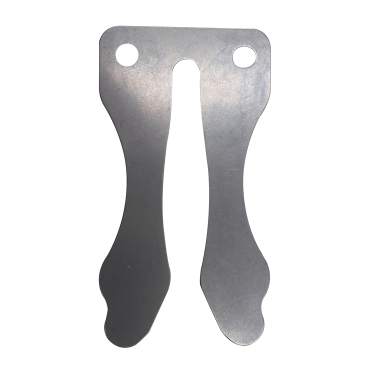
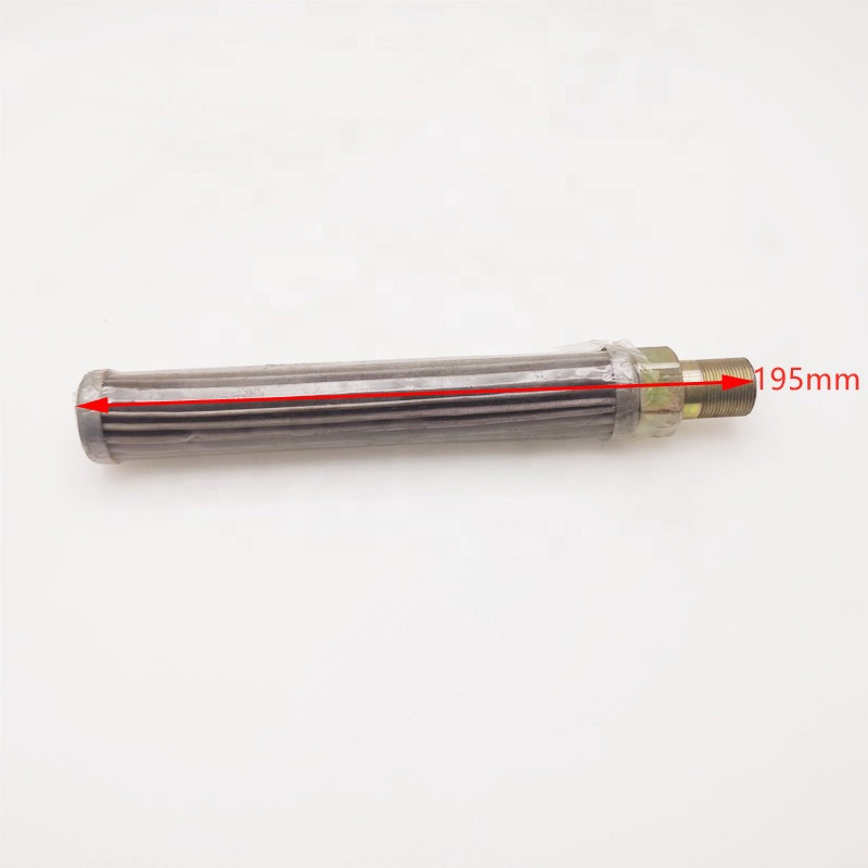
An impact wrench is used for disassembly of the two screws on the discharge, and the shutoff valve is loosened and the valve removed. The suction shutoff valve is also unscrewed and the suction gas filter in the middle of the housing cover is removed, to start with two screws at the top of the housing cover are removed two m10 parallel pins are mounted on opposite sides to ensure proper removal and prevent the cover from falling off at that point all other screws can be loosened the housing cover is loosened by carefully hitting it on the side with a rubber mallet and the cover pulled off over the parallel pins, below it is the rotor which is removed next now loosen the hexagon head screw of the rotor with the impact wrench and take off the balance weight pull the rotor out of the compressor housing using pliers, then pull the spacer sleeve off the eccentric shaft and remove it.
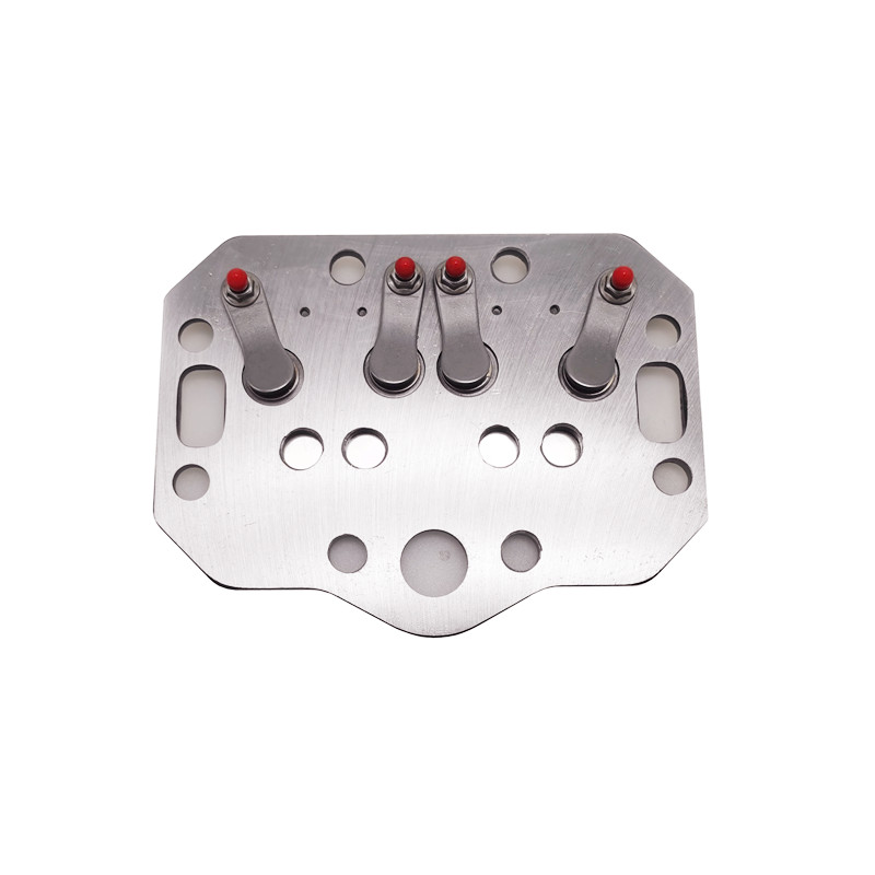
Mark the cylinders and valve plates using a water-soluble pen to avoid mixing them up when mounting them later on the screws of the cylinder heads opposite each other are loosened using the impact wrench the cylinder heads and valve plates can then be taken off the rubber mallet is hit lightly against the cylinder head and valve plate in order to loosen them.
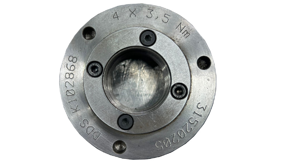
All the screws are removed using the impact wrench in order to take off the bearing cover the bearing cover is hit lightly with the rubber mallet to reduce the pressure of the eccentric shaft on the bearing cover take off the bearing cover and set it aside along with the bearing ring the screws on the oil centrifuge are loosened carefully removed the oil centrifuge and balance wait.
Now it’s time to remove the eccentric shaft carefully shift the connecting rods and pull the eccentric shaft out of the connecting rods with light turning movements in order to remove the cylinders the Pistons are first taken out of the cylinders one after the other and pulled from the inside and press from the outside, clean any oil residue from the Pistons and carefully place them on a soft surface to check a piston the zig rings are pulled off on both sides and the wrist pins removed.
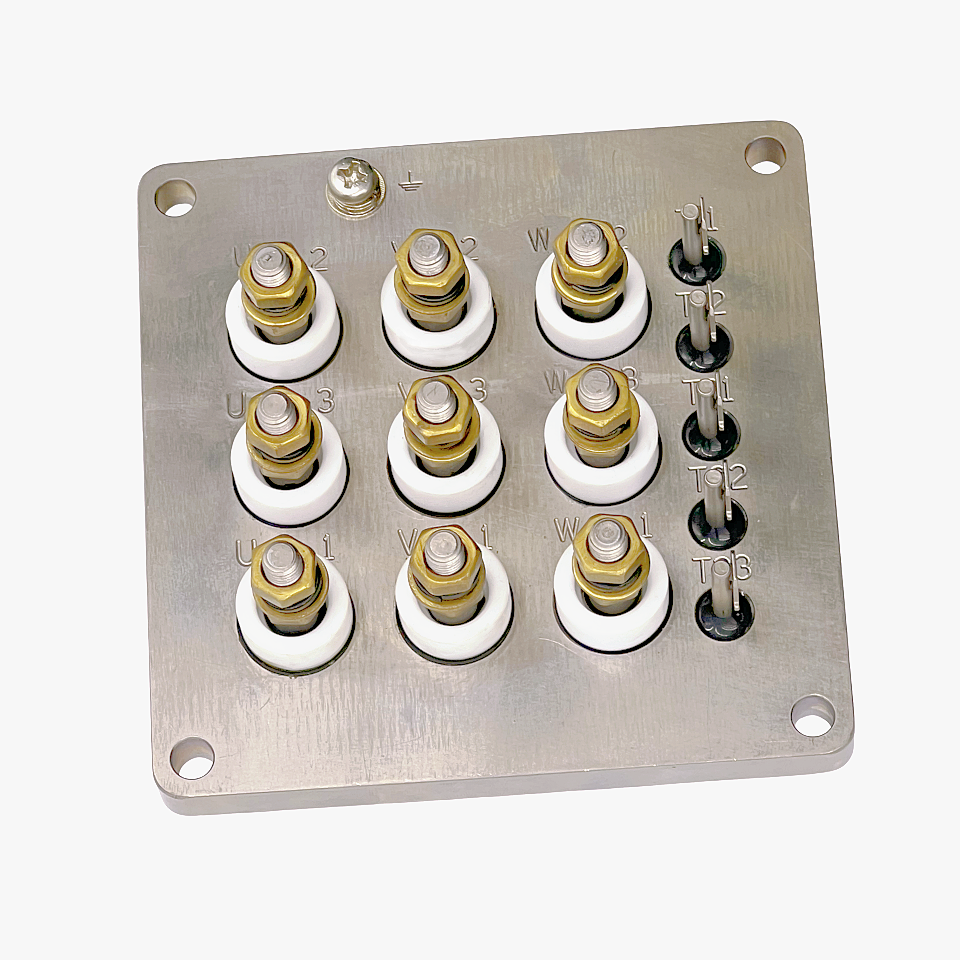
Loosen the screws on the terminal plate using the impact wrench the terminal plate can then be lifted pull off the cable lugs for the PTC sensor and then remove the six screws in the final step the terminal plate can now be removed.
I will show you how the stator is removed from the housing at the internal bits of service facility we screw the first part of our special tool and the stator together then we place the second device on the thread and a stator is pulled out slowly using hydraulics in the final step the stator is removed high-quality.